Magnetos
Internal Timing of Lucas SR1 Magneto.
- For a magneto to work successfully the contact breaker must open during a region where the change in magnetic flux is the greatest. This sounds complicated and fortunately on magnetos with rotating armatures the contact breaker plate is keyed to the coil assembly so this is not a problem. However the cam on the SR1 can be placed at any position relative to the rotating magnet and you can get into an awful mess.
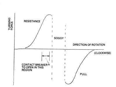
- If you rotate the armature of an assembled SR1 magneto, without either the contact breaker or cam fitted, you will feel two areas of resistance to rotation and two similar regions where the rotor is pulled by the magnetic flux. These are the periods where the changes of magnetic flux are the greatest. You have to choose the correct period. Again rotating the armature you will note that the region between pull and the resistance will feel soggy and slightly strange, the magnet is in line with the magnetic path through the coil.

- The contact breaker should be about to open immediately the resistance to rotation is felt after this period, see the sketch.. The optimum position varies slightly and will have to be found by trial and error.
- With everything assembled and the contact breaker tapped on to the taper at the chosen point clamp a short length of heavy gauge copper wire, or brazing rod, to the body by one of the end cap fixing screws so that there is about a 1 millimetre gap between end of the wire and the stud on the coil. If everything is correct, and the coil, condenser, contact breaker points etc. are in good condition; there should be a healthy spark when the armature is rocked backwards and forwards. The spark should occur in the direction of desired rotation (clockwise looking from the contact breaker side for an AMC single). The cam can be repositioned slightly, usually in an anticlockwise direction, to give the best spark. If there is a double spark it is likely that you have not chosen the correct region of magnetic flux change.
John Allen & Johnny Walker, July 1988
MAGNETO CARE
(FOR THE TYRO RESTORER)
- I know that it is all too easy too appear 'cocky' or supercilious when one has knowledge that the average Club member does not seem to possess but the one area of motorcycle maintenance that seems least understood - and therefore least attempted - lies in the electrical department. People who will happily discuss the merits and demerits of the effect of piston ring clearances and will attempt miraculous feats of hand-filing and dressing will shrug their shoulders and consign to the 'expert' a magneto which ceases to spark reliably when they have, (a) checked and cleaned the points, (b) checked and cleaned the HT pick-ups then, as a final despair, (c) cooked the whole magneto in the oven. There is an air of Black Magic about things electrical in many minds which seems to stem from the fact that whenever one meets devices which rely on magnetism, direct current, electromotive force or the like in a teaching situation the very next move seems to be to cover a blackboard with mathematical formulae. At this point many competent mechanical engineers switch off - and they rarely seem to get switched on again!
- Why am I entering upon this diatribe? Simply because I want to get the most important point understood. The magneto is a relatively straightforward device which relies almost totally on perfectly standard engineering practices to ensure perfect operation and your knowledge or understanding of all the complex formulae will make not a whit of difference as to whether you get the magneto working again! Any competent engineer capable of thorough cleaning, checking tolerances and meticulously reassembling components can usually get a viable spark from an ailing magneto. If you can't then at least you will have proved that there is something really wrong with the device and it will be worth giving it to the expert.
- How then does a magneto work? Built into the case of the magneto are magnets, permanent magnets. In early magnetos the magnets were formed from a cobalt material and had to be remagnetised if the armature was ever removed. The Lucas magdyno and magneto units fitted to all AMC machines after 1939 had Nifal magnets which are not demagnetised by removal of the armature.
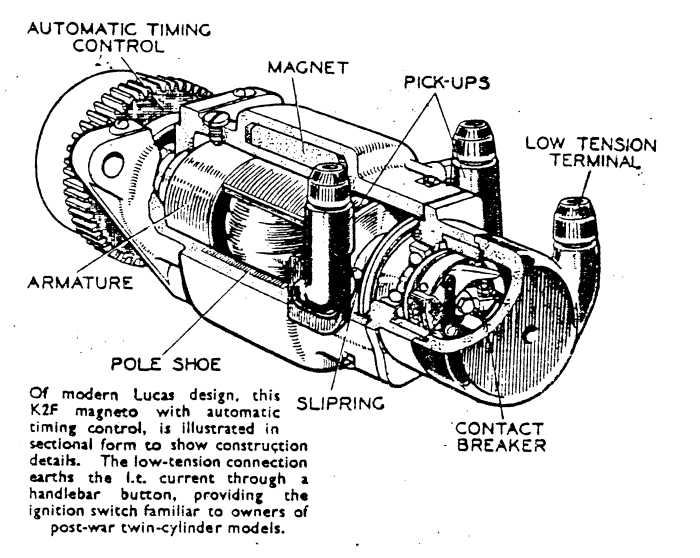
- In the centre of the magneto is a spinning armature, mounted in bearings at either end. The armature bears two sets of windings one of which acts as a generator of electricity which it applies to the contact breaker. At a defined point in the rotation of the engine the points open and one of the laws of nature performs its miracle. A high level of reverse electrical energy is formed which tries to prevent the points from opening. Instead of a few volts DC which is normally induced in the primary the reverse emf. can rise to hundreds of volts. Now this is the point at which we can start to affect the issue with our maintenance. The viability of that primary spark or voltage surge is dependant upon the state of the points. They should be clean and dry, equally the greatest surge comes when the break is instantaneous, so they should be square to each other where the 'break' is total, not angled, where it could be gradual. Also the value of the reverse surge is related to the amount of electricity generated in the primary, which is reduced by leakage if the armature is greasy or damp. The armature should be highly polished, ideally and the bearings run true so that the air gap between the magnet and the armature is constant. The bearings should run free but there should be minimal end-float an the armature. The adjustment is by adding or removing the square brass shims between the magneto body and the points housing. There should be a trace of grease - I prefer Vaseline - in the bearings and, even with the points in situ the magneto should spin freely with a slight rocking resistance caused at the point of maximum magnetic flux. So the magneto should be dismantled, carefully noting the order in which the parts fit. I recommend this order.
- Magneto off the machine, hold the drive sprocket with the drive chain and remove the centre nut then use a magneto puller to safeguard the taper on the drive shaft.
- Remove the points cover then the points, centre-bolt locates the points, on a face-cam magneto remove the outer point and spring assembly first. On all magnetos NEVER stop the points turning whilst removing the screw by holding the taper shaft.
- The vital step. Remove the HT pick-ups. Failure to do this can lead to impossible damage to the slip ring assembly. On twin magnetos also remove the safety gap screws (more later) which project into the slip ring assembly alongside the HT pick-ups. Remove the earth brush, under the label on the single and Wader mags, by the mounting flange on the twins.
- Remove the complete points cover and then the armature assembly can be withdrawn.
- With the magneto in bits in front of you, I hope (!), it is worth looking at the way the actual spark for the plug is generated.
- Having generated a low voltage source in the primary then breaking the circuit at the vital moment with the points a surge of high voltage is generated in the primary, which is usually around 200 turns of about 20 gauge copper wire. Around the pole of the armature is the secondary winding, about 12,000 turns in the standard magneto or 14,000 turns in a Wader, of very fine wire. That acts as a transformer and steps the voltage up to the level at, which it will jump across the plug gap to find its way to earth.
- And that is the second vital element in understanding just how to get your magneto to perform. Get the points clean, dry, square and the contact to the base of the points good. Then get a clean bright armature with constant air gap and you get maximum LT. The secondary will get the reverse surge up to a high enough voltage to jump to earth and you have to make sure that the only place that it can do that is across the plug points!
- On a single if there is a problem with the spark then the motor will stop but in a twin you can have one HT lead off but the engine will still run, the armature will still spin and the electrical energy will still be created for the duff lead. If there is no safety gap to get that current away to earth. it might burn out the armature secondary. That is where the screw alongside the HT pick-up comes in, it is a safety gap to earth which will absorb the extra energy rather than let your armature burn out. Don't lose the screws and don't put in longer ones. The gap to the slip ring is vital. If it is too small the spark will always take that easy route instead of jumping across the plug!
- Next area for examination should be the slip ring and HT pick-ups. There is a 'brush' in the base of the pick-up base my moisture or barbon dust, or a mixture of both. Make sure the brush slides in and out of the pick-up on its spring, freely. The brush bears on the slip ring and tends to wear away the brass contact strips. It is worth radiusing the contact base of the brush to minimise the way that it will cut the brass slip ring particularly at the leading edge of the brass strip. Dress the strip carefully with a Swiss file if it is stepped then lightly clean the brass surface with the finest grade of emery you can find. Ideally crocus paper should be used. Check the whole of the pick-up, it should be clean and shiny plastic/bakelite. In use they tend to 'track' with sparks running across the carbon dust which coats the brush holder outer surface. The action of the discharge through the carbon dust can be to heat up the film and bake a sort of conducting coating into the surface, make sure the whole assembly is thoroughly clean.
AJS and Matchless Owners Club Limited : https://WWW.JAMPOT.COM/
© 2000-2026 Jampot All Rights Reserved.
